The Black Box Test
For ELE 202 Circuits I
Introduction
A Black Box is actually a grey metal box with two terminals sticking out of it. Inside are two
passive components, one is a resistor and the other may be a capacitor or an inductor, and they
way they are connected may be either in series or in parallel. The point of the test is to use
a multimeter, a function generator, and an oscilloscope to determine what components are inside,
how they are connected, and their values, to within about 10%.
There are four possible cases; RC-series, RC-parallel, RL-series and RL-parallel. A good outline
was provided by Bob Marley:
 This testing procedure should allow to to identify the configuration and obtain the values.
Overview
There are up to three tests you need to do to find out what is actually inside the box - the Ohmmeter
Test, the Phase Shift Test, and the Inductor Test. Once you have determined which setup you
have, there are some frequency and phase measurements, followed by a few calculations, which
should give you your values and you can go home smiling.
Before we start: ELI the ICE man.
This handy but slightly gay acronym can help you remember the phase relationships between
voltage & current in inductors and capacitors. ELI means voltage leads current in
an inductor; this is because E comes before the L (leading), and I comes after the L
(lagging). ICE means current leads voltage in a capacitor; this is because
the I comes before the C (leading), and the E comes after the C (lagging).
Part One: How to Determine What the Box Contains
- The Ohmmeter Test. Place the ohmmeter across the terminals of the black box. If the meter starts off low but climbs quickly to read OL you know that this is an RC-series box. Skip ahead to the RC-series testing section. If the meter gives you a reading and stays there, scratch RC-series from your list. You are now down to 3 choices.
- The Phase Shift Test. Hook up a test circuit like this:
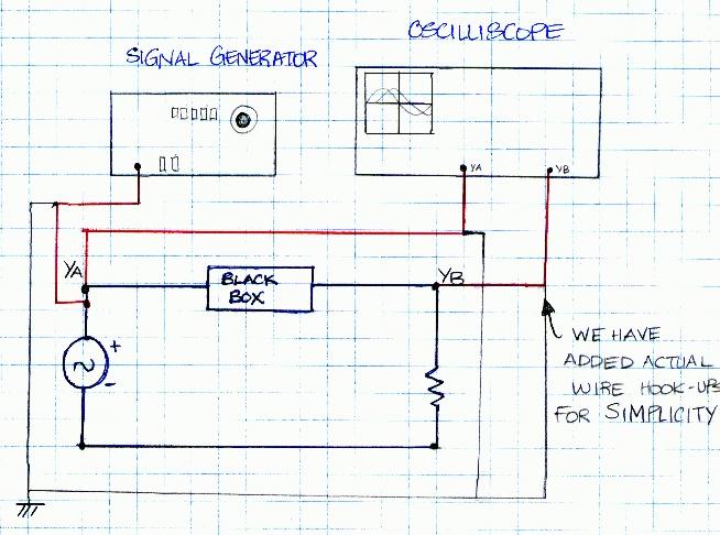
- Choose Rs to be small, about 20 ohms. It is just a sampling resistance and is used for measuring current in the circuit, according to:
- Turn on the scope & function generator, and MAKE SURE ALL THE CONTROLS ARE SET PROPERLY
i.e., all the knobs on the scope are turned over to CAL, the function generator gives a clean
sine output with no DC offset, both channel A and channel B read zero at no input, etc.
- Set the function generator for about a 1kHz sine wave at about 1Vp-p. The actual
voltage you choose isn't that important, just that blasting the box with 20Vp-p will
only load down the generator and possibly mess with your results.
- Display both channels on the scope and trigger off Channel A, set both channels to AC coupling.
Adjust the time divisions to display the largest full wave of channel A. Play with the
frequency until you get a good separation between the channel A and channel B waveforms.
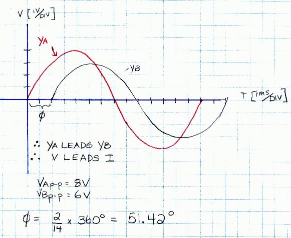
Now you have to determine whether VA or VB is the leading waveform. Remember ELI the ICE man! If voltage leads current then it is a circuit involving an inductor. If current leads voltage, it is a circuit involving a capacitor.
VA = channel A = voltage across test circuit
VB = channel B = current through test circuit
Example
If VB leads VA you know the circuit is RC-parallel - skip right to the RC-parallel testing section. If not, you know the circuit contains inductors. You are now down to two choices.
- Inductor Test. The only possibilities left are a series inductor or a parallel inductor.
- Case A: Parallel Inductor (RL-parallel)

- Set frequency to zero. At zero hertz, inductor is a short circuit (XL = 0), and therefore the box is a short circuit. Channel A waveform is the same as channel B waveform, i.e.
|VA| = |VB|
and the waveforms will be in phase.
- Set frequency to a high value, such as 20kHz. The impedance of the inductor will be high, nearing an open circuit (XL -> infinity). Channel A and channel B are in phase, but
|VA| > |VB|.
- Case B: Series Inductor (RL-series)
- Set frequency to zero. The inductor will become a short and only the resistor remains.
|VA| > |VB|
and the waveforms are in phase because it is s resistive circuit.
- Set frequency to a high value, such as 20kHz. The inductor will be open, thus I = 0.
VB = 0 (no current)
VA = function generator voltage
Part Two: How to Find the Values
Once you have distinguished which circuit you have you will now have to calculate the values as follows:
Case 1: RC-series
To find current: get the voltage VB from the oscilloscope. You may use peak or peak-to-peak values, but stay CONSISTENT. The circuit current is then:
To find the voltage (total voltage across test circuit):
You know:
- VA from oscilloscope
- I from VB / Rs
- Rs
thus you can find |Zbox|.
To find phase angle: count the divisions of 1 full waveform. Count the divisions between the leading & lagging waveforms, and the phase angle is then:
phase angle = # of divisions between leading and lagging wave x 360 degrees
              -----------------------------------------------
              # of divisions in one full waveform
You will now have a value
Thus you can calculate R and solve for C and you are done.
Case 2: RC-parallel
Follow the steps from the previous procedure to find VB, so you can calculate
I. Find VA, measure the frequency, measure the phase angle.
Now solve the capacitor expression for C and you are done.
Case 3: RL-series
Follow steps in previous cases to get values for VA, VB, current,
frequency, and phase angle.
Solve the inductor expression for L and you are done.
Case 4: RL-parallel
Do all steps as in previous cases to get values for VA, VB, current,
frequency, and phase angle.
Now solve the inductor expression for L and you are done.
REMEMBER
- Set input voltage to approximately 1 Vp-p.
- Use the meter to record frequency - if you use meter for measuring voltages, remember it gives
values in RMS!
- Use a sine wave signal
- Do not adjust the AMPLITUDE of the input signal after you have set the input voltage.
- All black wires go to the same place, which forms the circuit ground.
- Remember how to calculate using admittances in polar and rectangular forms.
- Highest frequency used should be around 30kHz.
- If VB leads VA remember your phase angle will be negative.
- Remember ELI the ICE man.
- And uh, TURN THE EQUIPMENT ON - duh?
Created 03-04-00 by the Department of Water and Power.